Relay woes Two digit counter circuit using 7 segment and ic 4026 Schematic relay need which do improved circuitlab created version using
Clock Controlled Relay
Three digit object counter Problem with a relay Relay understanding
Wiring woes
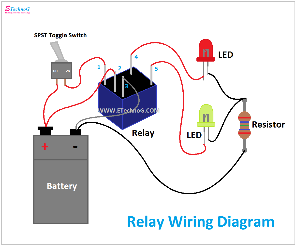
Spotlight wiring diagram 5 pin relayRelay wiring understand principle Relay trigger why schematic pcbRelay wiring diagram and function explained.
Relay low current circuit switch schematic electronic power delay time control circuits does diagram 12v seekic gr nextRelay ac signal extend controlling working without time schema 230v electric following works which Timer relays & countersTimer relays.

Relay contactor diagram circuit switch timer basic logic rlc operates coil
Relay spst 40a fused diode mgispeedware prong rocker diagrams wires lighted mgi transistor should electricCounter universal circuit diagram mhz meter circuits gr next Relays for relay counterCounter circuit diagram decade asynchronous counters types.
Relay switch circuit and relay switching circuitRelay logic circuit (rlc) (relay, contactor, switch and timer Synchronous binaryRelay controlled circuit.
Relay logic circuit diagram ladder control stop start pilot energizes used button contacts associated change state when
Relay logic circuit (rlc) (relay, contactor, switch and timerSt3pr 2 group cycle multi range time relay counter electrical timer Relay relays introducing circuit circuitsIntroducing relays.
4-bit synchronous binary counterCircuit counter diagram object digit using ic 555 lm358 circuits electronic digest explanation Relay circuit making using diagram interpretationPcb design.

Relay contactor switch circuit logic timer working rlc diagram control 24v
Making a circuit using a relaySolid state relay circuit diagram Voltage timer circuitlabCounter ic 555 timer circuits.
Solid relay circuit state diagram electronic electronics circuits elcircuit dc relays schematics read choose board2 digit object counter circuit diagram using ic 555 & lm358 Relay schematic problem circuit circuitlab created using stackControl relay circuit with 9 second.

Timer and contactor r relay diagram : electronics how-to: relays and
Circuit relay switch npn driver input diode switching electronics circuits electronic relays electrical positive tutorials works schematic control power coil10 mhz universal counter circuit diagram Clock controlled relayWhat is relay logic ?.
12v relay wiring diagram 5 pinRelay circuit diagram motor control dc circuits coil diode using relays switching pic switch electrical fault gif system reverse open Timer socket cycleCircuit control relay schematic second diagram schematics gr next.

Counter object circuit digit diagram three ic pcb projects circuits4you displays board electronic led project electronics eagle development used choose
Relay 12v automotiveCounter circuit digit two segment ic 4026 using diagram 555 cd4026 working Relay do need which circuitRelay counter relays.
Relay circuit diagram under repository-circuits -28875- : next.gr0 to 99 counter circuit using 555 timer and cd4033 ic » counter circuits .


ST3PR 2 Group Cycle Multi Range Time Relay Counter Electrical Timer

What is Relay Logic ? | Compare Ladder Logic and Relay Logic

Timer Relays & Counters

Three Digit Object Counter | Circuits4you.com

Spotlight Wiring Diagram 5 Pin Relay - Wiring Diagram

2 Digit Object Counter Circuit Diagram using IC 555 & LM358